
PARAMETRIC · 3D · STEP / STL / 3MF
Helical GearHELICAL GEAR
Enter normal module, teeth, helix angle and face width to preview a helical gear live and download STEP, STL or 3MF. Left/right hand, pressure angle, shift, backlash, D-cut and keyway bores.
- ProfileInvolute (normal basis)
- HandLeft / Right
- Helix angle0°–45°
- OutputSTEP · STL · 3MF · DXF
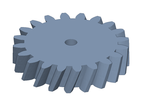
LIVE · HELICAL GEAR
m=2 · z=20 · β=20° R
SCALE 1:1 · mm
Drag to rotate · scroll to zoom · right-drag to pan
CALCULATED · SPEC
AUTO-COMPUTED
mt
2.1284mm
Transverse module
αt
21.173°
Transverse pressure angle
d
42.567mm
Pitch diameter
da
46.567mm
Tip diameter
df
37.567mm
Root diameter
db
39.694mm
Base diameter
pz
367.42mm
Lead
px
18.371mm
Axial pitch
θ
9.80°
Profile twist
εβ
0.544
Overlap ratio
zv
24.1
Virtual teeth
HOW-TO
How to generate a helical gear STEP / STL file
- 1Enter normal module, teeth and face width — the 3D view updates instantly.
- 2Set the helix angle and hand; the mating gear on a parallel shaft needs the opposite hand.
- 3Choose a bore type; for 3D printing set backlash and bore clearance under Print fit.
- 4Check the spec cards and any warnings.
- 5Download STEP, STL or 3MF — or send it to Orinovate for a quote.
What is a helical gear?
A helical gear has teeth cut along a helix at the helix angle β. Contact sweeps gradually across the face, so it runs quieter and carries more load than a spur gear — the standard in car gearboxes, speed reducers and high-speed drives. This tool works from the normal module and normal pressure angle (as a hob does) and twists the transverse involute profile along the lead, giving smooth tooth surfaces.
Key formulas
Transverse module mt = mn / cos β; transverse pressure angle αt = atan(tan αn / cos β); pitch diameter d = mt·z; tip diameter da = d + 2mn(1 + xn); root diameter df = d − 2mn(1.25 − xn); lead pz = π·d / tan β; axial pitch px = π·mn / sin β; overlap ratio εβ = b·sin β / (π·mn); virtual teeth zv = z / cos³β.
Specs at default parameters
| Parameter | Value | Range |
|---|---|---|
| Normal module (mn) | 2 mm | 0.3–10 |
| Teeth (z) | 20 | 6–200 |
| Helix angle (β) | 20 ° | 0–45 |
| Face width (b) | 10 mm | 1–100 |
| Normal pressure angle (αn) | 20° (standard) | 20° (standard) / 14.5° / 25° |
| Normal profile shift (xn) | 0 | -0.8–1 |
| Bore (d) | 5 mm | 0–100 |
| Bore type | Round | Round / D-cut / Keyway / Hex / Square |
| Backlash | 0 mm | 0–0.5 |
| Bore clearance | 0 mm | 0–1 |
| Hand | Right (R) | Right (R) / Left (L) |
| Transverse module (mt) | 2.1284 mm | — |
| Transverse pressure angle (αt) | 21.173 ° | — |
| Pitch diameter (d) | 42.567 mm | — |
| Tip diameter (da) | 46.567 mm | — |
| Root diameter (df) | 37.567 mm | — |
| Base diameter (db) | 39.694 mm | — |
| Lead (pz) | 367.42 mm | — |
| Axial pitch (px) | 18.371 mm | — |
| Profile twist (θ) | 9.80 ° | — |
| Overlap ratio (εβ) | 0.544 | — |
| Virtual teeth (zv) | 24.1 | — |
FAQ
What is the difference between normal and transverse module?
Measured perpendicular to the slanted teeth you get the normal module mn (what hobs and cutters are specified in); measured perpendicular to the axis you get the transverse module mt = mn / cos β. Pitch diameter d = mt × z, so an m2, 20-tooth gear with β = 20° has d = 42.57 mm instead of 40 mm.
How is the centre distance of two helical gears calculated?
Without profile shift a = mn × (z1 + z2) / (2 cos β). For mn2, 20 and 40 teeth, β = 20°: a = 2 × 60 / (2 × 0.9397) ≈ 63.85 mm. You can also tune β to land on a round centre distance.
How do I pair helical gears — left or right hand?
On parallel shafts both gears need the same normal module, normal pressure angle and helix angle, and opposite hands (one right, one left). Two gears of the same hand form a crossed-axis (90°) helical drive with point contact and much lower load capacity.
What about axial thrust?
A helical mesh produces an axial force Fa = Ft × tan β, growing with β. Use bearings that take thrust (angular-contact ball bearings or a thrust washer); if you want no thrust at all, use a double-helical (herringbone) gear.
Why 3D-print helical gears?
More teeth are in contact at once (overlap ratio εβ), so they run quieter and smoother than spur gears and tolerate FDM profile errors better. Helix angles of 15°–25° usually print without supports.
Which software opens the helical gear STEP file?
STEP (AP214) opens in Fusion 360, SolidWorks, FreeCAD, Onshape and Rhino. STL / 3MF import directly into Bambu Studio, PrusaSlicer or Cura.
Is it free?
Yes — no sign-up, no fees. Need a physical part? Send it to Orinovate for an instant quote in FDM, SLA, SLS, MJF or CNC.
Related generators
Related calculators
Related articles
- The complete guide to 3D-printed gears: materials, tolerances and processes2026-10-06
- How to calculate gear ratio: single-stage, compound and planetary gear ratio formulas (with torque and speed)2026-10-07
- Helical vs spur vs herringbone gears: contact ratio, axial thrust and module conversion compared2026-10-07
Need a physical part?
Send the model straight to Orinovate's instant quote: FDM, SLA, SLS, MJF, metal printing and CNC, made in Hsinchu, Taiwan.
About STEP / STL / 3MF / DXF
- STEP (.step / .stp, AP214) keeps exact dimensions and surfaces for editing in Fusion 360, SolidWorks or FreeCAD.
- STL and 3MF are triangle meshes that import directly into Bambu Studio, PrusaSlicer or Cura.
- DXF is the top-view 2D outline, ready for laser cutting, waterjet or CNC routing.
- All models are in millimetres at true scale.