
PARAMETRIC · 3D · STEP / STL / 3MF
Worm DriveWORM DRIVE
Generate a meshing worm and worm wheel on crossed 90° axes at a = (d₁+d₂)/2, with matching module, starts and hand. Efficiency and self-locking are estimated; download both as STEP, STL or 3MF.
- Ratioi = z₂ / z₁
- Self-lockingtan γ vs μ
- OutputSTEP · STL · 3MF · DXF
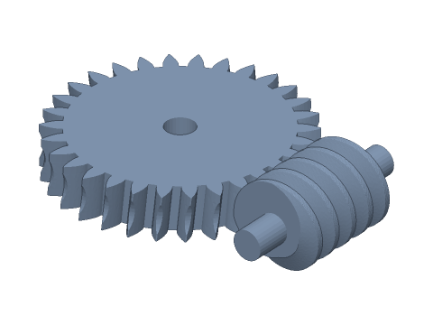
LIVE · WORM DRIVE
m=2 · 30:1 · i=30 RH
SCALE 1:1 · mm
Drag to rotate · scroll to zoom · right-drag to pan
CALCULATED · SPEC
AUTO-COMPUTED
a
40.00mm
Centre distance
i
30.00
Ratio
γ
5.71°
Lead angle
tan γ
0.100
Self-locking check (locks if tan γ < μ)
η (μ=0.05)
65%
Forward efficiency (worm driving)
η' (μ=0.05)
47%
Back-drive efficiency (0 = self-locking)
d₁
20.00mm
Worm pitch diameter
d₂
60.00mm
Wheel pitch diameter
da₁
24.00mm
Worm tip diameter
de₂
66.00mm
Wheel outside diameter
pz
6.283mm
Lead
L
50.0mm
Worm overall length
HOW-TO
How to generate a worm drive STEP / STL file
- 1Enter the module, worm starts, wheel teeth and diameter quotient q — the viewport shows worm and wheel in mesh.
- 2Set the thread length, wheel width, hand and throat, then the shafts and bores.
- 3For 3D printing, apply backlash and extra centre distance.
- 4Check the spec cards and any warnings.
- 5Download STEP, STL or 3MF — or send it to Orinovate for a quote.
Meshing conditions of a worm drive
The worm's axial module equals the wheel's transverse module m, the worm lead angle γ equals the wheel helix angle β, both have the same hand and the axes cross at 90°. Worm pitch diameter d₁ = q·m, wheel pitch diameter d₂ = z₂·m, centre distance a = (d₁+d₂)/2 and ratio i = z₂ / z₁. The tool puts the wheel on the Z axis and the worm parallel to Y on the wheel's mid-plane, turning the worm so a thread groove faces a wheel tooth.
Efficiency and self-locking
A worm drive works mostly by sliding, so efficiency depends on lead angle and friction: η = tan γ / tan(γ + ρ'), with ρ' = atan(μ / cos αn). A smaller lead angle gives a larger ratio for the same wheel but lower efficiency; once tan γ < μ the back-drive efficiency drops to zero and the wheel cannot turn the worm — useful for holding lifts, gates, winches and rotary tables in position.
Specs at default parameters
| Parameter | Value | Range |
|---|---|---|
| Module (m) | 2 mm | 0.5–6 |
| Worm starts (z₁) | 1 | 1–4 |
| Wheel teeth (z₂) | 30 | 10–150 |
| Diameter quotient (q) | 10 | 6–20 |
| Hand | Right hand | Right hand / Left hand |
| Worm thread length (b₁) | 30 mm | 2–150 |
| Wheel face width (b₂) | 12 mm | 1–80 |
| Wheel throat | Throated (torus) | Throated (torus) / None (plain helical) |
| Worm shaft diameter | 8 mm | 0–60 |
| Worm shaft length | 10 mm | 0–200 |
| Worm bore | 0 mm | 0–60 |
| Wheel bore | 8 mm | 0–200 |
| Backlash | 0.05 mm | 0–0.5 |
| Extra centre distance | 0 mm | 0–1 |
| Centre distance (a) | 40.00 mm | — |
| Ratio (i) | 30.00 | — |
| Lead angle (γ) | 5.71 ° | — |
| Self-locking check (locks if tan γ < μ) (tan γ) | 0.100 | — |
| Forward efficiency (worm driving) (η (μ=0.05)) | 65 % | — |
| Back-drive efficiency (0 = self-locking) (η' (μ=0.05)) | 47 % | — |
| Worm pitch diameter (d₁) | 20.00 mm | — |
| Wheel pitch diameter (d₂) | 60.00 mm | — |
| Worm tip diameter (da₁) | 24.00 mm | — |
| Wheel outside diameter (de₂) | 66.00 mm | — |
| Lead (pz) | 6.283 mm | — |
| Worm overall length (L) | 50.0 mm | — |
FAQ
Is the worm drive self-locking, and how can I tell?
Compare the lead angle γ = atan(z₁/q) with the friction angle ρ' = atan(μ / cos αn): when tan γ is below the friction coefficient μ, the wheel cannot back-drive the worm (static self-locking). Typical μ: lubricated steel on bronze 0.03–0.05, greased POM or nylon 0.05–0.1, dry PLA/PETG 0.15 or more. The spec cards show tan γ and the back-drive efficiency at μ = 0.05 — 0 % means self-locking. The default single start with q = 10 has tan γ = 0.1: back-drivable when well lubricated, usually locking as dry plastic. Vibration can defeat self-locking, so add a brake for anything safety-related.
How efficient is it?
Forward efficiency η = tan γ / tan(γ + ρ'). At μ = 0.05: about 65 % for one start (γ ≈ 5.7°), 78 % for two (γ ≈ 11.3°) and 86 % for four (γ ≈ 21.8°). The rest becomes heat, so watch lubrication and temperature in continuous duty; for printed parts use POM or nylon with grease — PLA can soften from friction heat.
What matters when assembling it?
Centre distance a = (d₁+d₂)/2 — for m2, q10 and 30 teeth, a = (20 + 60) ÷ 2 = 40 mm — and the worm axis must sit on the mid-plane of the wheel face, exactly as in the model. Worm and wheel have the same hand. The worm carries an axial load roughly equal to the wheel's tangential force, so locate it with bearings or thrust washers that take axial load on both ends.
How accurate is the wheel tooth form?
Real worm wheels are hobbed with a cutter shaped like the worm, so their teeth envelope it. This tool approximates the wheel as an involute helical gear with helix angle γ plus a toroidal throat: it meshes correctly in the central plane and the two solids do not interfere at the default backlash — fine for 3D printing, housing design and assembly checks. For heavy or precision duty, hob the wheel or let printed parts run in.
Which software opens the worm drive STEP file?
STEP (AP214) opens in Fusion 360, SolidWorks, FreeCAD, Onshape and Rhino. STL / 3MF import directly into Bambu Studio, PrusaSlicer or Cura.
Is it free?
Yes — no sign-up, no fees. Need a physical part? Send it to Orinovate for an instant quote in FDM, SLA, SLS, MJF or CNC.
Related generators
Related calculators
Need a physical part?
Send the model straight to Orinovate's instant quote: FDM, SLA, SLS, MJF, metal printing and CNC, made in Hsinchu, Taiwan.
About STEP / STL / 3MF / DXF
- STEP (.step / .stp, AP214) keeps exact dimensions and surfaces for editing in Fusion 360, SolidWorks or FreeCAD.
- STL and 3MF are triangle meshes that import directly into Bambu Studio, PrusaSlicer or Cura.
- DXF is the top-view 2D outline, ready for laser cutting, waterjet or CNC routing.
- All models are in millimetres at true scale.