
PARAMETRIC · 3D · STEP / STL / 3MF
Spur Gear PairSPUR GEAR PAIR
Generate two meshing spur gears at the correct centre distance (profile shift included), preview the mesh and download both as STEP, STL or 3MF.
- PairingAuto centre distance
- ShiftPer gear
- OutputSTEP · STL · 3MF · DXF
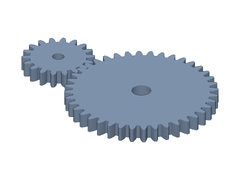
LIVE · SPUR GEAR PAIR
m=1.5 · 18:40
SCALE 1:1 · mm
Drag to rotate · scroll to zoom · right-drag to pan
CALCULATED · SPEC
AUTO-COMPUTED
a
43.500mm
Centre distance
i
2.222
Ratio
D₁
27.00mm
Driver pitch dia.
D₂
60.00mm
Driven pitch dia.
Da₁
30.00mm
Driver tip dia.
Da₂
63.00mm
Driven tip dia.
HOW-TO
How to generate a spur gear pair STEP / STL file
- 1Enter the module and both tooth counts — the viewport shows the mesh.
- 2Set shifts, bores and print clearance if needed.
- 3Check the spec cards and any warnings.
- 4Download STEP, STL or 3MF — or send it to Orinovate for a quote.
Designing a gear pair
A spur pair needs the same module and pressure angle, the right centre distance and a contact ratio above about 1.2. Ratio i = z₂ / z₁; output torque ≈ input × i × 0.98. Small pinions often take positive shift to avoid undercut and strengthen the root.
Specs at default parameters
| Parameter | Value | Range |
|---|---|---|
| Module (m) | 1.5 mm | 0.3–10 |
| Driver teeth (z₁) | 18 | 6–200 |
| Driven teeth (z₂) | 40 | 6–200 |
| Face width (b) | 6 mm | 0.5–100 |
| Pressure angle (α) | 20° (standard) | 20° (standard) / 14.5° / 25° |
| Driver shift (x₁) | 0 | -0.8–1 |
| Driven shift (x₂) | 0 | -0.8–1 |
| Driver bore | 5 mm | 0–100 |
| Driven bore | 8 mm | 0–100 |
| Backlash | 0.05 mm | 0–0.5 |
| Extra centre distance | 0 mm | 0–1 |
| Centre distance (a) | 43.500 mm | — |
| Ratio (i) | 2.222 | — |
| Driver pitch dia. (D₁) | 27.00 mm | — |
| Driven pitch dia. (D₂) | 60.00 mm | — |
| Driver tip dia. (Da₁) | 30.00 mm | — |
| Driven tip dia. (Da₂) | 63.00 mm | — |
FAQ
Why generate both gears together?
They are placed at the right centre distance and phase, so the STEP doubles as an assembly reference for checking size, interference and housing space.
How is the shifted centre distance found?
The working pressure angle is solved from both shift coefficients, then a = m(z₁+z₂)/2 × cos α / cos α'. It appears in the spec cards.
Can I download them separately?
They export as two separate bodies you can pick in CAD. For a single gear, use the spur gear generator with the same values.
Which software opens the gear pair STEP file?
STEP (AP214) opens in Fusion 360, SolidWorks, FreeCAD, Onshape and Rhino. STL / 3MF import directly into Bambu Studio, PrusaSlicer or Cura.
Is it free?
Yes — no sign-up, no fees. Need a physical part? Send it to Orinovate for an instant quote in FDM, SLA, SLS, MJF or CNC.
Related generators
Related calculators
Related articles
- How to calculate gear ratio: single-stage, compound and planetary gear ratio formulas (with torque and speed)2026-10-07
- Bevel gear design guide: pitch cone angle, cone distance, face width and straight vs spiral bevel gears2026-10-07
- Planetary gearbox design: tooth count rules, gear ratio calculation and 3D printing tips (with valid tooth combinations)2026-10-07
Need a physical part?
Send the model straight to Orinovate's instant quote: FDM, SLA, SLS, MJF, metal printing and CNC, made in Hsinchu, Taiwan.
About STEP / STL / 3MF / DXF
- STEP (.step / .stp, AP214) keeps exact dimensions and surfaces for editing in Fusion 360, SolidWorks or FreeCAD.
- STL and 3MF are triangle meshes that import directly into Bambu Studio, PrusaSlicer or Cura.
- DXF is the top-view 2D outline, ready for laser cutting, waterjet or CNC routing.
- All models are in millimetres at true scale.