
PARAMETRIC · 3D · STEP / STL / 3MF
Bevel Gear PairBEVEL GEAR PAIR
Generate a meshing straight bevel gear and pinion on a 90° shaft angle with a shared pitch-cone apex and matched phase. Cone angles, cone distance and mounting distances are computed; download both as STEP, STL or 3MF.
- Shaft angle90°
- Cone apexShared, auto-aligned
- OutputSTEP · STL · 3MF · DXF
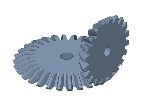
LIVE · BEVEL GEAR PAIR
m=2 · 20:30 · Σ=90°
SCALE 1:1 · mm
Drag to rotate · scroll to zoom · right-drag to pan
CALCULATED · SPEC
AUTO-COMPUTED
δ₁
33.690°
Pinion pitch cone angle
δ₂
56.310°
Gear pitch cone angle
R
36.056mm
Cone distance
i
1.500
Ratio
d₁
40.00mm
Pinion pitch dia.
d₂
60.00mm
Gear pitch dia.
da₁
43.328mm
Pinion outer dia.
da₂
62.219mm
Gear outer dia.
A₁
30.00mm
Pinion: apex to back face
A₂
20.00mm
Gear: apex to back face
zv₁
24.0
Pinion virtual teeth
zv₂
54.1
Gear virtual teeth
R/3
12.02mm
Recommended max. face width
HOW-TO
How to generate a bevel gear pair STEP / STL file
- 1Enter the module and both tooth counts — cone angles and cone distance are computed automatically.
- 2Set the face width (≤ R/3), bores and print backlash; the viewport shows the 90° mesh.
- 3Check the spec cards and any warnings.
- 4Download STEP, STL or 3MF — or send it to Orinovate for a quote.
Straight bevel gear pairs
Bevel gears transmit power between intersecting shafts (90° here). Their pitch cones touch along one element and share an apex. The cone angles follow from the ratio, tan δ₁ = z₁ / z₂; the large-end pitch diameter is d = m·z and the cone distance R = d / (2 sin δ). This tool places the gear on the Z axis and the pinion on the X axis with coincident apexes, turning the pinion half a pitch for an even tooth count so a tooth space faces a gear tooth.
Face width and tooth form
Teeth use Tredgold's back-cone approximation: the large-end profile is the involute of the virtual spur gear on the back cone (zv = z / cos δ), all tooth elements converge on the apex and the small end is a scaled copy of the large end. Keep the face width ≤ R/3 — wider faces leave tiny, weak small-end teeth — and watch for undercut when zv is small.
Specs at default parameters
| Parameter | Value | Range |
|---|---|---|
| Module (m) | 2 mm | 0.3–10 |
| Pinion teeth (z₁) | 20 | 6–150 |
| Gear teeth (z₂) | 30 | 6–150 |
| Face width (b) | 10 mm | 0.5–100 |
| Pressure angle (α) | 20° (standard) | 20° (standard) / 14.5° / 25° |
| Pinion bore | 6 mm | 0–100 |
| Gear bore | 8 mm | 0–100 |
| Backlash | 0.05 mm | 0–0.5 |
| Pinion pitch cone angle (δ₁) | 33.690 ° | — |
| Gear pitch cone angle (δ₂) | 56.310 ° | — |
| Cone distance (R) | 36.056 mm | — |
| Ratio (i) | 1.500 | — |
| Pinion pitch dia. (d₁) | 40.00 mm | — |
| Gear pitch dia. (d₂) | 60.00 mm | — |
| Pinion outer dia. (da₁) | 43.328 mm | — |
| Gear outer dia. (da₂) | 62.219 mm | — |
| Pinion: apex to back face (A₁) | 30.00 mm | — |
| Gear: apex to back face (A₂) | 20.00 mm | — |
| Pinion virtual teeth (zv₁) | 24.0 | — |
| Gear virtual teeth (zv₂) | 54.1 | — |
| Recommended max. face width (R/3) | 12.02 mm | — |
FAQ
How are the cone angles and cone distance calculated?
For a 90° shaft angle, tan δ₁ = z₁ / z₂ and δ₂ = 90° − δ₁; the cone distance is R = m·√(z₁² + z₂²) / 2. For m2 and 20:30: δ₁ = atan(20/30) = 33.69°, δ₂ = 56.31° and R = √1300 ≈ 36.06 mm. Both pitch cones must share one apex — the intersection of the shafts — to mesh correctly across the face.
Where do the two gears go when assembling?
Measure from the shaft intersection (the cone apex): the pinion's back face sits A₁ = R·cos δ₁ = d₂/2 from it and the gear's back face A₂ = R·cos δ₂ = d₁/2. The A₁ and A₂ spec cards are the locating dimensions for the housing and bearing seats; an axial offset on either gear gives uneven backlash or binding, so shim to fine-tune.
Why generate them as a pair? Can I mix gears from different sets?
A bevel gear's cone angle and tooth form depend on the ratio of the pair: a 20-tooth gear has a 45° cone when it meets 20 teeth but 33.69° when it meets 30, so they are not interchangeable. Decide z₁ and z₂ together — the two gears generated here are a matched set.
Do bevel gears create axial thrust?
Yes. In a straight bevel mesh both gears are pushed away from the cone apex: pinion axial force Fa₁ = Ft·tan α·sin δ₁, gear Fa₂ = Ft·tan α·sin δ₂ (Ft = tangential force near the large-end pitch circle). Both shafts need bearings or thrust shoulders that take axial load, otherwise the gears are pushed apart and backlash grows.
Which software opens the bevel gear pair STEP file?
STEP (AP214) opens in Fusion 360, SolidWorks, FreeCAD, Onshape and Rhino. STL / 3MF import directly into Bambu Studio, PrusaSlicer or Cura.
Is it free?
Yes — no sign-up, no fees. Need a physical part? Send it to Orinovate for an instant quote in FDM, SLA, SLS, MJF or CNC.
Related generators
Related calculators
Need a physical part?
Send the model straight to Orinovate's instant quote: FDM, SLA, SLS, MJF, metal printing and CNC, made in Hsinchu, Taiwan.
About STEP / STL / 3MF / DXF
- STEP (.step / .stp, AP214) keeps exact dimensions and surfaces for editing in Fusion 360, SolidWorks or FreeCAD.
- STL and 3MF are triangle meshes that import directly into Bambu Studio, PrusaSlicer or Cura.
- DXF is the top-view 2D outline, ready for laser cutting, waterjet or CNC routing.
- All models are in millimetres at true scale.