
PARAMETRIC · 3D · STEP / STL / 3MF
Bevel GearBEVEL GEAR
Enter module, pinion and gear teeth, face width and bore to preview a 90° straight bevel gear and download STEP, STL or 3MF. Output either member; cone angles and cone distance are computed for you.
- ProfileStraight (Tredgold)
- Shaft angle90°
- Output partGear / Pinion
- OutputSTEP · STL · 3MF · DXF
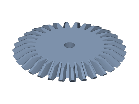
LIVE · BEVEL GEAR
m=2 · 20:30 · z=30
SCALE 1:1 · mm
Drag to rotate · scroll to zoom · right-drag to pan
CALCULATED · SPEC
AUTO-COMPUTED
δ
56.310°
Pitch cone angle
δ'
33.690°
Mate cone angle
R
36.056mm
Cone distance
d1
40.00mm
Pinion pitch diameter
d2
60.00mm
Gear pitch diameter
da
62.219mm
Outside diameter
i
1.500
Gear ratio
zv
54.1
Virtual teeth
H
5.55mm
Toothed axial height
R/3
12.02mm
Recommended max face width
HOW-TO
How to generate a bevel gear STEP / STL file
- 1Enter the module and the pinion and gear tooth counts of the pair.
- 2Choose gear or pinion as the output and set the face width (≤ cone distance / 3).
- 3Set the bore and print fit; switch Output part to generate the mate.
- 4Check the spec cards and any warnings.
- 5Download STEP, STL or 3MF — or send it to Orinovate for a quote.
What is a bevel gear?
A bevel gear has teeth on a cone and transmits motion between intersecting shafts, most often at 90° — hand drills, differentials, right-angle drives and robot joints. The pitch-cone apexes of the pair coincide at the shaft intersection and the tooth ratio sets the cone angles. This tool builds straight bevel gears with Tredgold's back-cone approximation and outputs either the gear or the pinion.
Key formulas
Cone angles δ1 = atan(z1 / z2), δ2 = 90° − δ1; pitch diameter d = m·z; cone distance R = m·√(z1² + z2²) / 2; outside diameter da = m·(z + 2 cos δ); virtual teeth zv = z / cos δ; toothed axial height = b·cos δ; small-to-large end scale = (R − b) / R.
Specs at default parameters
| Parameter | Value | Range |
|---|---|---|
| Module (m) | 2 mm | 0.3–10 |
| Pinion teeth (z1) | 20 | 6–150 |
| Gear teeth (z2) | 30 | 6–150 |
| Output part | Gear (z2) | Gear (z2) / Pinion (z1) |
| Face width (b) | 10 mm | 0.5–100 |
| Pressure angle (α) | 20° (standard) | 20° (standard) / 14.5° / 25° |
| Bore (d) | 6 mm | 0–100 |
| Bore type | Round | Round / D-cut / Keyway / Hex / Square |
| Backlash | 0 mm | 0–0.5 |
| Bore clearance | 0 mm | 0–1 |
| Pitch cone angle (δ) | 56.310 ° | — |
| Mate cone angle (δ') | 33.690 ° | — |
| Cone distance (R) | 36.056 mm | — |
| Pinion pitch diameter (d1) | 40.00 mm | — |
| Gear pitch diameter (d2) | 60.00 mm | — |
| Outside diameter (da) | 62.219 mm | — |
| Gear ratio (i) | 1.500 | — |
| Virtual teeth (zv) | 54.1 | — |
| Toothed axial height (H) | 5.55 mm | — |
| Recommended max face width (R/3) | 12.02 mm | — |
FAQ
How are the cone angles calculated?
For a 90° shaft angle the pinion cone angle δ1 = atan(z1 / z2) and the gear δ2 = 90° − δ1. For 20:30, δ1 = 33.69° and δ2 = 56.31°. Both cone apexes must meet at the shaft intersection for a correct mesh.
Why enter both tooth counts?
Bevel gears are designed in pairs: a 30-tooth gear for a 20-tooth pinion has a different cone angle than one for a 15-tooth pinion, so they are not interchangeable. Fix z1 and z2, then output each member. With z1 = z2 (miter gears) both are identical.
Why limit face width to 1/3 of the cone distance?
Teeth shrink toward the apex; a wide face leaves tiny, weak small-end teeth that are hard to cut. Common design practice (AGMA, Gleason) is b ≤ R/3 or 10m, whichever is smaller, with cone distance R = m·√(z1² + z2²) / 2.
How do I mount bevel gears?
Shafts at 90°, with the back cones aligned: the pinion's large-end pitch plane sits d2 / 2 from the gear axis and vice versa. Mounting-distance errors cause tip interference or excess backlash — shim the axial position to adjust.
How accurate is the tooth form?
It uses Tredgold's approximation: the large-end profile is the involute of the virtual spur gear on the back cone (zv = z / cos δ) and every tooth element converges on the apex (tapered depth). Outside diameter, cone angles and cone distance are exact — fine for 3D printing, prototypes and slow drives; precision production uses spherical-involute or Gleason forms.
Which software opens the bevel gear STEP file?
STEP (AP214) opens in Fusion 360, SolidWorks, FreeCAD, Onshape and Rhino. STL / 3MF import directly into Bambu Studio, PrusaSlicer or Cura.
Is it free?
Yes — no sign-up, no fees. Need a physical part? Send it to Orinovate for an instant quote in FDM, SLA, SLS, MJF or CNC.
Related generators
Related calculators
Related articles
Need a physical part?
Send the model straight to Orinovate's instant quote: FDM, SLA, SLS, MJF, metal printing and CNC, made in Hsinchu, Taiwan.
About STEP / STL / 3MF / DXF
- STEP (.step / .stp, AP214) keeps exact dimensions and surfaces for editing in Fusion 360, SolidWorks or FreeCAD.
- STL and 3MF are triangle meshes that import directly into Bambu Studio, PrusaSlicer or Cura.
- DXF is the top-view 2D outline, ready for laser cutting, waterjet or CNC routing.
- All models are in millimetres at true scale.