
PARAMETRIC · 3D · STEP / STL / 3MF
Helical RackHELICAL RACK
Enter normal module, teeth, height, face width and helix angle to preview a helical rack and download STEP, STL or 3MF. Meshes with a helical gear of the same module and helix angle; quieter than a straight rack.
- ProfileISO 53 basic rack (normal)
- HandLeft / Right
- OutputSTEP · STL · 3MF · DXF
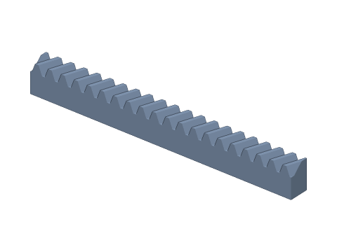
LIVE · HELICAL RACK
m=2 · 20T · β=20° R
SCALE 1:1 · mm
Drag to rotate · scroll to zoom · right-drag to pan
CALCULATED · SPEC
AUTO-COMPUTED
pt
6.686mm
Transverse pitch
pn
6.283mm
Normal pitch
mt
2.1284mm
Transverse module
αt
21.173°
Transverse pressure angle
L
133.73mm
Rack length
hp
13.00mm
Pitch-line height
h
4.50mm
Whole depth
b·tanβ
3.64mm
Offset across face
HOW-TO
How to generate a helical rack STEP / STL file
- 1Enter the normal module (same as the helical gear) and tooth count.
- 2Set height, face width, helix angle and hand.
- 3For 3D printing, add backlash.
- 4Check the spec cards and any warnings.
- 5Download STEP, STL or 3MF — or send it to Orinovate for a quote.
What is a helical rack?
A helical rack has teeth slanted at the helix angle β — a helical gear with infinite pitch radius. Meshed with a helical pinion it converts rotation into linear motion with contact sweeping across the face, running quieter and stiffer than a straight rack; it is the usual drive for fast gantries and long-travel CNC machines. This tool converts the normal ISO 53 basic rack into the transverse profile, extrudes it obliquely across the face and trims both ends square.
Key formulas
Transverse pitch pt = π·mn / cos β; transverse pressure angle αt = atan(tan αn / cos β); length L = teeth × pt; pitch-line height = H − mn; whole depth h = 2.25 mn; offset across the face = b·tan β; travel per pinion revolution = π·mn·z / cos β.
Specs at default parameters
| Parameter | Value | Range |
|---|---|---|
| Normal module (mn) | 2 mm | 0.3–10 |
| Teeth | 20 | 1–300 |
| Overall height (H) | 15 mm | 1–200 |
| Face width (b) | 10 mm | 0.5–100 |
| Helix angle (β) | 20 ° | 0–45 |
| Hand | Right (R) | Right (R) / Left (L) |
| Normal pressure angle (αn) | 20° (standard) | 20° (standard) / 14.5° / 25° |
| Backlash | 0 mm | 0–0.5 |
| Transverse pitch (pt) | 6.686 mm | — |
| Normal pitch (pn) | 6.283 mm | — |
| Transverse module (mt) | 2.1284 mm | — |
| Transverse pressure angle (αt) | 21.173 ° | — |
| Rack length (L) | 133.73 mm | — |
| Pitch-line height (hp) | 13.00 mm | — |
| Whole depth (h) | 4.50 mm | — |
| Offset across face (b·tanβ) | 3.64 mm | — |
FAQ
Which gear meshes with a helical rack?
A helical gear with the same normal module, normal pressure angle and helix angle, of the opposite hand: right-hand rack with left-hand gear and vice versa. Gear centre to rack base = (H − mn) + mn·z / (2 cos β).
Why isn't the length a multiple of π·m?
Along the rack you measure the transverse pitch pt = π·mn / cos β. For mn2, β20°: pt = 6.687 mm, so 20 teeth are 133.73 mm long. Tune β if you want a round travel per revolution.
Helical or straight rack?
A helical rack has more teeth in contact, so it is quieter and smoother — the choice for fast CNC routers, laser cutters and gantries. It produces a sideways thrust Fa = Ft·tan β, so the rack needs lateral support. For light, slow 3D-printed mechanisms a straight rack is enough.
Can I join segments?
Yes. Ends are cut square and whole tooth counts keep the pitch continuous; because the teeth slant, the joint splits a tooth, so align segments with dowels before fixing them.
Which software opens the helical rack STEP file?
STEP (AP214) opens in Fusion 360, SolidWorks, FreeCAD, Onshape and Rhino. STL / 3MF import directly into Bambu Studio, PrusaSlicer or Cura.
Is it free?
Yes — no sign-up, no fees. Need a physical part? Send it to Orinovate for an instant quote in FDM, SLA, SLS, MJF or CNC.
Related generators
Related calculators
Related articles
Need a physical part?
Send the model straight to Orinovate's instant quote: FDM, SLA, SLS, MJF, metal printing and CNC, made in Hsinchu, Taiwan.
About STEP / STL / 3MF / DXF
- STEP (.step / .stp, AP214) keeps exact dimensions and surfaces for editing in Fusion 360, SolidWorks or FreeCAD.
- STL and 3MF are triangle meshes that import directly into Bambu Studio, PrusaSlicer or Cura.
- DXF is the top-view 2D outline, ready for laser cutting, waterjet or CNC routing.
- All models are in millimetres at true scale.