
PARAMETRIC · 3D · STEP / STL / 3MF
Worm WheelWORM WHEEL
Enter module, teeth, worm pitch diameter and starts to preview a worm wheel live and download STEP, STL or 3MF. Centre distance and lead angle are computed; throat, hand and keyway bores supported.
- ProfileHelical involute + throat
- HandRight / Left
- Centre distanceAuto
- OutputSTEP · STL · 3MF · DXF
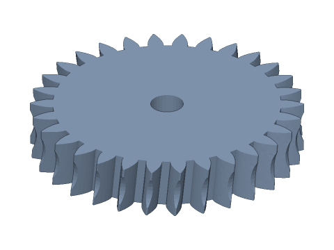
LIVE · WORM WHEEL
m=2 · z2=30 · i=30
SCALE 1:1 · mm
Drag to rotate · scroll to zoom · right-drag to pan
CALCULATED · SPEC
AUTO-COMPUTED
d2
60.00mm
Pitch diameter
da2
64.00mm
Throat diameter
de2
66.00mm
Outside diameter
df2
55.00mm
Root diameter
a
40.00mm
Centre distance
i
30.0
Ratio
γ
5.71°
Lead (helix) angle
mn
1.990mm
Normal module
HOW-TO
How to generate a worm wheel STEP / STL file
- 1Enter module, teeth and the mating worm's pitch diameter and starts.
- 2Set face width, hand and throat — the spec cards show centre distance and lead angle.
- 3Choose the bore; for 3D printing apply backlash and bore clearance.
- 4Check the spec cards and any warnings.
- 5Download STEP, STL or 3MF — or send it to Orinovate for a quote.
What is a worm wheel?
A worm wheel is the helical gear that meshes with a worm on a crossed (90°) axis. A single worm stage gives 10–100:1, runs quietly and can self-lock, so it is used in winches, lifts, valves and rotary stages. This tool models a helical involute wheel with transverse module m and helix angle equal to the worm lead angle, with an optional throat.
Key formulas
Pitch diameter d2 = m·z2; throat diameter da2 = d2 + 2m; outside diameter de2 ≈ da2 + m (1–2 starts); root diameter df2 = d2 − 2.5m; centre distance a = (d1 + d2) / 2; lead angle γ = atan(z1·m / d1); ratio i = z2 / z1; throat radius = d1/2 − m.
Specs at default parameters
| Parameter | Value | Range |
|---|---|---|
| Module (m) | 2 mm | 0.5–6 |
| Teeth (z2) | 30 | 10–150 |
| Worm pitch diameter (d1) | 20 mm | 3–120 |
| Worm starts (z1) | 1 | 1–4 |
| Face width (b2) | 12 mm | 1–80 |
| Hand | Right hand | Right hand / Left hand |
| Throat | Throated | Throated / None (plain helical) |
| Bore (d) | 8 mm | 0–200 |
| Bore type | Round | Round / D-cut / Keyway / Hex / Square |
| Backlash | 0 mm | 0–0.5 |
| Bore clearance | 0 mm | 0–1 |
| Pitch diameter (d2) | 60.00 mm | — |
| Throat diameter (da2) | 64.00 mm | — |
| Outside diameter (de2) | 66.00 mm | — |
| Root diameter (df2) | 55.00 mm | — |
| Centre distance (a) | 40.00 mm | — |
| Ratio (i) | 30.0 | — |
| Lead (helix) angle (γ) | 5.71 ° | — |
| Normal module (mn) | 1.990 mm | — |
FAQ
What centre distance do the worm and wheel need?
a = (d1 + d2) / 2 with d1 the worm pitch diameter and d2 = m·z2. For m2, d1 = 20 and 30 teeth: a = 40 mm. Align the worm axis with the middle of the wheel face.
Why are the wheel teeth inclined?
The worm thread has a lead angle γ, so the wheel teeth must be inclined by the same helix angle β = γ to mesh. It is computed as γ = atan(z1·m / d1); the hand must match the worm.
What does the throat do?
A throated wheel wraps around the worm, lengthening the contact line and increasing load capacity. Here the throat is cut by a torus (worm tip + clearance revolved around the wheel axis). A true hobbed flank is a conjugate surface; this tool approximates it with a helical involute, which suits 3D printing and light loads.
Which material for a worm wheel?
Industrial drives pair a phosphor-bronze wheel with a hardened steel worm. For 3D printing use PETG, nylon (PA) or POM-like resins with grease, and watch heat build-up at high speed.
Which software opens the worm wheel STEP file?
STEP (AP214) opens in Fusion 360, SolidWorks, FreeCAD, Onshape and Rhino. STL / 3MF import directly into Bambu Studio, PrusaSlicer or Cura.
Is it free?
Yes — no sign-up, no fees. Need a physical part? Send it to Orinovate for an instant quote in FDM, SLA, SLS, MJF or CNC.
Related generators
Related calculators
Related articles
Need a physical part?
Send the model straight to Orinovate's instant quote: FDM, SLA, SLS, MJF, metal printing and CNC, made in Hsinchu, Taiwan.
About STEP / STL / 3MF / DXF
- STEP (.step / .stp, AP214) keeps exact dimensions and surfaces for editing in Fusion 360, SolidWorks or FreeCAD.
- STL and 3MF are triangle meshes that import directly into Bambu Studio, PrusaSlicer or Cura.
- DXF is the top-view 2D outline, ready for laser cutting, waterjet or CNC routing.
- All models are in millimetres at true scale.