
PARAMETRIC · 3D · STEP / STL / 3MF
Double Helical GearDOUBLE HELICAL GEAR
Enter normal module, teeth, helix angle and face width to preview a herringbone (double helical) gear and download STEP, STL or 3MF. Axial thrust cancels out; optional centre groove and bore types.
- ProfileInvolute (normal basis)
- Axial thrustCancelled
- Centre grooveOptional
- OutputSTEP · STL · 3MF · DXF
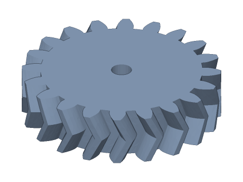
LIVE · DOUBLE HELICAL GEAR
m=2 · z=20 · β=±25°
SCALE 1:1 · mm
Drag to rotate · scroll to zoom · right-drag to pan
CALCULATED · SPEC
AUTO-COMPUTED
mt
2.2068mm
Transverse module
αt
21.880°
Transverse pressure angle
d
44.135mm
Pitch diameter
da
48.135mm
Tip diameter
df
39.135mm
Root diameter
db
40.956mm
Base diameter
pz
297.35mm
Lead
px
14.867mm
Axial pitch
θ
7.26°
Twist per half
εβ
0.807
Overlap ratio
zv
26.9
Virtual teeth
b/2
6.00mm
Half face width
HOW-TO
How to generate a double helical gear STEP / STL file
- 1Enter normal module, teeth and total face width.
- 2Set the helix angle; add a centre groove if it will be hobbed or to avoid the sharp apex.
- 3Choose the bore type and print fit.
- 4Check the spec cards and any warnings.
- 5Download STEP, STL or 3MF — or send it to Orinovate for a quote.
What is a double helical gear?
A double helical (herringbone) gear has two helical halves of opposite hand, so the teeth form a V. It keeps the quiet running and high load capacity of helical gears while cancelling axial thrust — used in large reducers, rolling mills, marine gearboxes and turbine drives. This tool twists the transverse involute along the lead for the lower half and mirrors it for the upper half, with an optional centre groove.
Key formulas
As for helical gears: mt = mn / cos β; d = mt·z; da = d + 2mn(1 + xn); df = d − 2mn(1.25 − xn); twist per half θ = (b − g)/2 · tan β / (d/2); overlap ratio over the total face εβ = b·sin β / (π·mn).
Specs at default parameters
| Parameter | Value | Range |
|---|---|---|
| Normal module (mn) | 2 mm | 0.3–10 |
| Teeth (z) | 20 | 6–200 |
| Helix angle (β) | 25 ° | 5–45 |
| Total face width (b) | 12 mm | 2–100 |
| Normal pressure angle (αn) | 20° (standard) | 20° (standard) / 14.5° / 25° |
| Normal profile shift (xn) | 0 | -0.8–1 |
| Bore (d) | 5 mm | 0–100 |
| Bore type | Round | Round / D-cut / Keyway / Hex / Square |
| Backlash | 0 mm | 0–0.5 |
| Bore clearance | 0 mm | 0–1 |
| Centre groove (g) | 0 mm | 0–50 |
| Transverse module (mt) | 2.2068 mm | — |
| Transverse pressure angle (αt) | 21.880 ° | — |
| Pitch diameter (d) | 44.135 mm | — |
| Tip diameter (da) | 48.135 mm | — |
| Root diameter (df) | 39.135 mm | — |
| Base diameter (db) | 40.956 mm | — |
| Lead (pz) | 297.35 mm | — |
| Axial pitch (px) | 14.867 mm | — |
| Twist per half (θ) | 7.26 ° | — |
| Overlap ratio (εβ) | 0.807 | — |
| Virtual teeth (zv) | 26.9 | — |
| Half face width (b/2) | 6.00 mm | — |
FAQ
How does it differ from a helical gear?
A herringbone gear is a right-hand and a left-hand helical gear joined back to back. The axial forces Fa = Ft·tan β of the halves are equal and opposite, so they cancel — allowing large helix angles (30°–45°) and high overlap without thrust bearings.
How do I pair herringbone gears?
Use the same normal module, normal pressure angle and helix angle with the V pointing the opposite way (flip one of two generated gears). Centre distance a = mn × (z1 + z2) / (2 cos β). Usually only one shaft is located axially; the other floats so the mesh self-centres.
What is the centre groove for?
A hob cannot cut a continuous V, so industrial double helical gears have a relief groove in the middle. 3D printing or 5-axis milling can make a true grooveless herringbone — set the groove to 0. A groove also cleans up the sharp apex on prints.
Why 3D-print herringbone gears?
They self-centre and won't walk axially, and the symmetric V keeps overhangs balanced so FDM prints need no supports — ideal for planetary sets, extruder drives and display gearboxes.
Which software opens the double helical gear STEP file?
STEP (AP214) opens in Fusion 360, SolidWorks, FreeCAD, Onshape and Rhino. STL / 3MF import directly into Bambu Studio, PrusaSlicer or Cura.
Is it free?
Yes — no sign-up, no fees. Need a physical part? Send it to Orinovate for an instant quote in FDM, SLA, SLS, MJF or CNC.
Related generators
Related calculators
Related articles
Need a physical part?
Send the model straight to Orinovate's instant quote: FDM, SLA, SLS, MJF, metal printing and CNC, made in Hsinchu, Taiwan.
About STEP / STL / 3MF / DXF
- STEP (.step / .stp, AP214) keeps exact dimensions and surfaces for editing in Fusion 360, SolidWorks or FreeCAD.
- STL and 3MF are triangle meshes that import directly into Bambu Studio, PrusaSlicer or Cura.
- DXF is the top-view 2D outline, ready for laser cutting, waterjet or CNC routing.
- All models are in millimetres at true scale.