
PARAMETRIC · 3D · STEP / STL / 3MF
Helical Gear PairHELICAL GEAR PAIR
Generate two meshing helical gears: the driven gear automatically takes the opposite hand and sits at a = mn(z₁+z₂)/(2cos β), profile shift included. Preview the mesh and download both as STEP, STL or 3MF.
- HandDriven gear auto-opposite
- Centre distanceAuto, with shift
- OutputSTEP · STL · 3MF · DXF
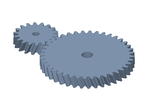
LIVE · HELICAL GEAR PAIR
m=1.5 · 18:40 · β=20° R/L
SCALE 1:1 · mm
Drag to rotate · scroll to zoom · right-drag to pan
CALCULATED · SPEC
AUTO-COMPUTED
a
46.292mm
Centre distance
i
2.222
Ratio
mt
1.5963mm
Transverse module
αwt
21.173°
Transverse working pressure angle
tan β
0.364
Axial thrust factor Fa/Ft
β₂
LH
Driven-gear hand
d₁
28.733mm
Driver pitch dia.
d₂
63.851mm
Driven pitch dia.
da₁
31.733mm
Driver tip dia.
da₂
66.851mm
Driven tip dia.
εα
1.493
Transverse contact ratio
εβ
0.581
Overlap ratio
HOW-TO
How to generate a helical gear pair STEP / STL file
- 1Enter the normal module, both tooth counts and the helix angle, then pick the driver's hand.
- 2Set shifts, bores and print clearance if needed — the viewport shows both gears in mesh.
- 3Check the spec cards and any warnings.
- 4Download STEP, STL or 3MF — or send it to Orinovate for a quote.
Meshing conditions for a helical pair
A parallel-axis helical pair needs the same normal module mn, normal pressure angle αn and helix angle β, with opposite hands. In the transverse section mt = mn / cos β and tan αt = tan αn / cos β, so d = mt·z and a = mt(z₁+z₂)/2. This tool aligns a driver tooth with a driven tooth space in the z = 0 section (turning the driven gear half a pitch for an even tooth count); the two gears then twist in opposite directions across the face, so every section stays in correct mesh.
Contact ratio and axial thrust
The total contact ratio is εγ = εα + εβ: the transverse ratio εα is computed as for spur gears, while the overlap ratio εβ grows with face width and helix angle — which is why helical gears run quieter and carry more load than spur gears. The price is axial thrust Fa = Ft·tan β; the spec cards show tan β as the thrust factor for sizing bearings.
Specs at default parameters
| Parameter | Value | Range |
|---|---|---|
| Normal module (mn) | 1.5 mm | 0.3–10 |
| Driver teeth (z₁) | 18 | 6–200 |
| Driven teeth (z₂) | 40 | 6–200 |
| Helix angle (β) | 20 ° | 0–45 |
| Driver hand | Right hand (driven: left) | Right hand (driven: left) / Left hand (driven: right) |
| Face width (b) | 8 mm | 1–100 |
| Normal pressure angle (αn) | 20° (standard) | 20° (standard) / 14.5° / 25° |
| Driver normal shift (xn₁) | 0 | -0.8–1 |
| Driven normal shift (xn₂) | 0 | -0.8–1 |
| Driver bore | 5 mm | 0–100 |
| Driven bore | 8 mm | 0–100 |
| Backlash | 0.05 mm | 0–0.5 |
| Extra centre distance | 0 mm | 0–1 |
| Centre distance (a) | 46.292 mm | — |
| Ratio (i) | 2.222 | — |
| Transverse module (mt) | 1.5963 mm | — |
| Transverse working pressure angle (αwt) | 21.173 ° | — |
| Axial thrust factor Fa/Ft (tan β) | 0.364 | — |
| Driven-gear hand (β₂) | LH | — |
| Driver pitch dia. (d₁) | 28.733 mm | — |
| Driven pitch dia. (d₂) | 63.851 mm | — |
| Driver tip dia. (da₁) | 31.733 mm | — |
| Driven tip dia. (da₂) | 66.851 mm | — |
| Transverse contact ratio (εα) | 1.493 | — |
| Overlap ratio (εβ) | 0.581 | — |
FAQ
Why must the driven gear have the opposite hand?
On parallel shafts the teeth of both gears must lie along the same line where they touch: a right-hand driver needs a left-hand driven gear (and vice versa) for line contact across the face. Two gears of the same hand only mesh on crossed shafts (crossed helical / spiral gears), a point-contact drive with much lower load capacity.
How is the helical centre distance calculated?
Without shift, a = mn(z₁+z₂)/(2cos β). For mn 1.5, 18:40 and β 20°: a = 1.5 × 58 ÷ (2 × 0.9397) ≈ 46.29 mm. With shift, solve the transverse working pressure angle from inv αwt = 2(xn₁+xn₂)·tan αn/(z₁+z₂) + inv αt, then a = a₀·cos αt / cos αwt. Conversely, you can hit a fixed, non-round centre distance by fine-tuning β.
How large is the axial thrust and which bearings do I need?
Fa = Ft·tan β, where Ft = 2T/d is the tangential force at the pitch circle. At β = 20°, tan β ≈ 0.36, so about 36 % of the tangential force pushes each gear along its shaft — in opposite directions on the two gears. Use deep-groove or angular-contact bearings that take axial load and locate the gears with shoulders or circlips. If the thrust is unacceptable, a double-helical (herringbone) gear cancels it.
Which helix angle should I choose?
Usually 8°–25°. The overlap ratio εβ = b·sin β / (π·mn) rises with β and face width, making the drive quieter and stronger, at the cost of more thrust. Printed gears commonly use 15°–20° for a clear noise reduction; with b ≥ π·mn / sin β, εβ ≥ 1 and at least one tooth is always in contact.
Which software opens the helical gear pair STEP file?
STEP (AP214) opens in Fusion 360, SolidWorks, FreeCAD, Onshape and Rhino. STL / 3MF import directly into Bambu Studio, PrusaSlicer or Cura.
Is it free?
Yes — no sign-up, no fees. Need a physical part? Send it to Orinovate for an instant quote in FDM, SLA, SLS, MJF or CNC.
Related generators
Related calculators
Need a physical part?
Send the model straight to Orinovate's instant quote: FDM, SLA, SLS, MJF, metal printing and CNC, made in Hsinchu, Taiwan.
About STEP / STL / 3MF / DXF
- STEP (.step / .stp, AP214) keeps exact dimensions and surfaces for editing in Fusion 360, SolidWorks or FreeCAD.
- STL and 3MF are triangle meshes that import directly into Bambu Studio, PrusaSlicer or Cura.
- DXF is the top-view 2D outline, ready for laser cutting, waterjet or CNC routing.
- All models are in millimetres at true scale.