
PARAMETRIC · 3D · STEP / STL / 3MF
Spur Gear m=1.5 · z=60SPUR GEAR
Free STEP, STL and 3MF download of a spur gear m=1.5 · z=60 with live 3D preview. Key dimensions: Pitch diameter 90.00 mm, Tip diameter 93.00 mm, Root diameter 86.25 mm, Circular pitch 4.712 mm. Every parameter stays adjustable, and you can send it straight to Orinovate for printing.
- ProfileInvolute
- Pressure angle14.5° / 20° / 25°
- Profile shiftYes
- OutputSTEP · STL · 3MF · DXF
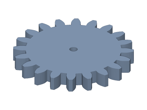
LIVE · SPUR GEAR
m=1.5 · z=60
SCALE 1:1 · mm
Drag to rotate · scroll to zoom · right-drag to pan
CALCULATED · SPEC
AUTO-COMPUTED
D
90.00mm
Pitch diameter
Da
93.00mm
Tip diameter
Df
86.25mm
Root diameter
p
4.712mm
Circular pitch
Db
84.57mm
Base diameter
s
2.356mm
Tooth thickness
sa
1.178mm
Tip thickness
zmin
18
Min. teeth w/o undercut
HOW-TO
How to generate a spur gear STEP / STL file
- 1Enter module, teeth and face width — the 3D view updates instantly.
- 2Set bore type, hub and set-screw hole if needed.
- 3For 3D printing, set backlash and bore clearance under Print fit, or apply the FDM preset.
- 4Check the spec cards (pitch, tip and root diameters) and any warnings.
- 5Download STEP, STL or 3MF — or send it straight to Orinovate for a print quote.
What is a spur gear?
A spur gear is a cylindrical gear whose teeth run parallel to the axis. It is the simplest and most common gear, with 98–99 % efficiency, used in gearboxes, robots, 3D printers and DIY mechanisms. This tool models true involute flanks as smooth surfaces, not polygons.
Key formulas
Pitch diameter D = m·z; tip diameter Da = m·(z + 2 + 2x); root diameter Df = m·(z − 2.5 + 2x); base diameter Db = D·cos α; circular pitch p = π·m — where m is module, z teeth, x profile shift and α pressure angle.
Specs at default parameters
| Parameter | Value | Range |
|---|---|---|
| Module (m) | 1.5 mm | 0.1–10 |
| Teeth (z) | 60 | 6–200 |
| Face width (b) | 9 mm | 0.5–100 |
| Pressure angle (α) | 20° (standard) | 20° (standard) / 14.5° / 25° |
| Profile shift (x) | 0 | -0.8–1 |
| Bore (d) | 5 mm | 0–100 |
| Bore type | Round | Round / D-cut / Keyway / Hex / Square |
| Hub diameter | 0 mm | 0–200 |
| Hub length | 5 mm | 0–100 |
| Set-screw hole | None | None / M2 / M3 / M4 / M5 |
| Backlash | 0 mm | 0–0.5 |
| Bore clearance | 0 mm | 0–1 |
| Pitch diameter (D) | 90.00 mm | — |
| Tip diameter (Da) | 93.00 mm | — |
| Root diameter (Df) | 86.25 mm | — |
| Circular pitch (p) | 4.712 mm | — |
| Base diameter (Db) | 84.57 mm | — |
| Tooth thickness (s) | 2.356 mm | — |
| Tip thickness (sa) | 1.178 mm | — |
| Min. teeth w/o undercut (zmin) | 18 | — |
Popular spur gear sizes
- m=0.5 · z=12
- m=0.5 · z=15
- m=0.5 · z=20
- m=0.5 · z=24
- m=0.5 · z=30
- m=0.5 · z=40
- m=0.5 · z=60
- m=1 · z=12
- m=1 · z=15
- m=1 · z=20
- m=1 · z=24
- m=1 · z=30
- m=1 · z=40
- m=1 · z=60
- m=1.5 · z=12
- m=1.5 · z=15
- m=1.5 · z=20
- m=1.5 · z=24
- m=1.5 · z=30
- m=1.5 · z=40
- m=1.5 · z=60
- m=2 · z=12
- m=2 · z=15
- m=2 · z=20
- m=2 · z=24
- m=2 · z=30
- m=2 · z=40
- m=2 · z=60
FAQ
How do I choose the module?
A larger module means bigger, stronger teeth. Small 3D-printed mechanisms usually use m0.8–m1.5; for FDM, m ≥ 1 prints cleanly. Meshing gears must share module and pressure angle.
How is the centre distance calculated?
Without profile shift, a = m × (z1 + z2) / 2. For m2 with 20 and 40 teeth: a = 2 × 60 / 2 = 60 mm. Profile shift changes it — use the spur gear centre distance calculator.
Why shift small gears?
With a 20° pressure angle, gears below 17 teeth are undercut by the generating cutter, weakening the root. A positive shift (e.g. x = 0.3 for 12 teeth) avoids it.
STEP or STL?
STEP keeps exact surfaces for editing in Fusion 360, SolidWorks or FreeCAD. STL / 3MF are triangle meshes for slicers.
What clearance for 3D-printed gears?
FDM: about 0.1 mm backlash and 0.2 mm bore clearance. SLA: 0.05 / 0.1 mm. SLS: 0.1 / 0.15 mm. Tune for your machine and material.
Is it free?
Yes — no sign-up, no fees. Need a real part? Send it to Orinovate for an instant quote in FDM, SLA, SLS, MJF or CNC.
Related generators
Related calculators
Related articles
- Gear module explained: choosing a module for 3D printing and DIY2026-10-06
- The complete guide to 3D-printed gears: materials, tolerances and processes2026-10-06
- 3D-printed hole tolerances: why holes shrink and how much clearance to add2026-10-06
- Rack and pinion: a design guide to turning rotation into linear motion2026-10-06
- Helical vs spur vs herringbone gears: contact ratio, axial thrust and module conversion compared2026-10-07
- Design for 3D printing: minimum wall thickness, 45° overhangs, supports, hole tolerances and FDM vs SLA vs SLS vs MJF2026-10-07
- Planetary gearbox design: tooth count rules, gear ratio calculation and 3D printing tips (with valid tooth combinations)2026-10-07
Need a physical part?
Send the model straight to Orinovate's instant quote: FDM, SLA, SLS, MJF, metal printing and CNC, made in Hsinchu, Taiwan.
About STEP / STL / 3MF / DXF
- STEP (.step / .stp, AP214) keeps exact dimensions and surfaces for editing in Fusion 360, SolidWorks or FreeCAD.
- STL and 3MF are triangle meshes that import directly into Bambu Studio, PrusaSlicer or Cura.
- DXF is the top-view 2D outline, ready for laser cutting, waterjet or CNC routing.
- All models are in millimetres at true scale.