
PARAMETRIC · 3D · STEP / STL / 3MF
SprocketSPROCKET
Pick a roller chain size (No.25–80), tooth count and type to preview a sprocket live and download STEP, STL or 3MF. ISO 606 / JIS B 1801 tooth form with side chamfer, hubs and keyway bores.
- StandardISO 606 / JIS B 1801
- ChainNo.25–80
- TypeA / B / C
- OutputSTEP · STL · 3MF · DXF
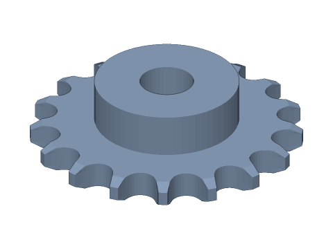
LIVE · SPROCKET
No.40 · 17T
SCALE 1:1 · mm
Drag to rotate · scroll to zoom · right-drag to pan
CALCULATED · SPEC
AUTO-COMPUTED
dp
69.12mm
Pitch diameter
do
75.56mm
Outside diameter
df
61.20mm
Root diameter
dc
60.90mm
Caliper diameter
dg
54.6mm
Max. hub diameter
t
7.2mm
Tooth width
p
12.700mm
Chain pitch
d1
7.92mm
Roller diameter
HOW-TO
How to generate a sprocket STEP / STL file
- 1Choose the chain number and tooth count — the ISO tooth form updates live.
- 2Pick type A / B / C and set the hub diameter and length (within the max hub diameter shown).
- 3Set bore and bore type; add bore clearance for 3D printing.
- 4Check the spec cards and any warnings.
- 5Download STEP, STL or 3MF — or send it to Orinovate for a quote.
What is a sprocket?
A sprocket is a toothed wheel that meshes with roller chain, transmitting power in motorcycles, bicycles, conveyors and machinery with an exact ratio over long centre distances and no slip. This tool follows the ISO 606 / JIS B 1801 tooth form: roller seating radius ri = 0.505·d1 + 0.069·d1^(1/3), flank radius re = 0.12·d1·(z + 2) and seating angle α = 120° − 90°/z.
Key formulas
Pitch diameter dp = p / sin(180°/z); outside diameter do = p·(0.6 + cot(180°/z)); root diameter df = dp − d1; caliper diameter dc = df (even z) or dp·cos(90°/z) − d1 (odd z); max hub diameter dg = p·cot(180°/z) − 1.04·h2 − 0.76 (h2 = inner plate depth).
Specs at default parameters
| Parameter | Value | Range |
|---|---|---|
| Chain number | No.40 (12.7 mm) | No.25 (6.35 mm) / No.35 (9.525 mm) / No.40 (12.7 mm) / No.50 (15.875 mm) / No.60 (19.05 mm) / No.80 (25.4 mm) |
| Teeth (z) | 17 | 9–150 |
| Sprocket type | Type B (one hub) | Type A (plate) / Type B (one hub) / Type C (two hubs) |
| Hub diameter | 40 mm | 4–400 |
| Hub length | 12 mm | 0–100 |
| Bore (d) | 15 mm | 0–300 |
| Bore type | Round | Round / Keyway / D-cut |
| Tooth side chamfer | ISO chamfer | ISO chamfer / None |
| Bore clearance | 0 mm | 0–1 |
| Pitch diameter (dp) | 69.12 mm | — |
| Outside diameter (do) | 75.56 mm | — |
| Root diameter (df) | 61.20 mm | — |
| Caliper diameter (dc) | 60.90 mm | — |
| Max. hub diameter (dg) | 54.6 mm | — |
| Tooth width (t) | 7.2 mm | — |
| Chain pitch (p) | 12.700 mm | — |
| Roller diameter (d1) | 7.92 mm | — |
Popular sprocket sizes
FAQ
How do I calculate the sprocket pitch diameter?
dp = p / sin(180° / z), with p the chain pitch and z the teeth. No.40 (p = 12.7 mm), 17 teeth: dp = 12.7 / sin(10.588°) = 69.12 mm; outside diameter do = p·(0.6 + cot(180°/z)) = 75.56 mm.
What is the caliper diameter?
The inspection dimension across the tooth gaps. For even tooth counts measure across opposite gaps: dc = df. Odd counts have no opposite gap, so measure the nearest ones: dc = dp·cos(90°/z) − d1.
How many teeth should a sprocket have?
Fewer teeth increase chordal action (speed ripple and noise). Use at least 13, preferably 17 or more, and 21+ for high speed or heavy load. Keep the ratio under 7:1 and the centre distance around 30–50 pitches.
Can I 3D print a sprocket?
For low speed and light load (robots, bike prototypes) PETG, nylon or PA-CF work well; tooth width follows the JIS single-strand table. Use steel or CNC for heavy loads. The roller seat uses the ISO maximum tooth-gap form, which tolerates print error.
Which software opens the sprocket STEP file?
STEP (AP214) opens in Fusion 360, SolidWorks, FreeCAD, Onshape and Rhino. STL / 3MF import directly into Bambu Studio, PrusaSlicer or Cura.
Is it free?
Yes — no sign-up, no fees. Need a physical part? Send it to Orinovate for an instant quote in FDM, SLA, SLS, MJF or CNC.
Related generators
Related calculators
Related articles
Need a physical part?
Send the model straight to Orinovate's instant quote: FDM, SLA, SLS, MJF, metal printing and CNC, made in Hsinchu, Taiwan.
About STEP / STL / 3MF / DXF
- STEP (.step / .stp, AP214) keeps exact dimensions and surfaces for editing in Fusion 360, SolidWorks or FreeCAD.
- STL and 3MF are triangle meshes that import directly into Bambu Studio, PrusaSlicer or Cura.
- DXF is the top-view 2D outline, ready for laser cutting, waterjet or CNC routing.
- All models are in millimetres at true scale.